| Terry L Koberstein: Packaging
Scientist for Del Monte Foods:
Linkedin.com
	Terry Koberstein
Location: San Francisco Bay Area
Industry: Food & Beverages
Current
  Packaging Engineer at Del Monte Foods
Education
  Brigham Young University
Packaging Digest, Desiccant Dried up Del Monte Damate
Protecting primary packages from condensation and moisture damage when shipping
product halfway across the globe is no easy feat. Pineapple canned at its
source in the Philippines by San Francisco based Del Monte Foods underwent
lengthy, month-long voyages through extreme climates from tropical to arctic
before reaching U.S. and other destinations, mostly without incident. But
in 1993 Mother Nature threw Del Monte a curve ball in the form of altered
weather patterns, and cans inside the overseas cargo containers began sustaining
extensive moisture damage, despite being packed in corrugated containers,
stacked on pallets and unitized with stretch wrap. "We found heavy amounts
of rust on the cans, and discoloration of the paper labels," says Terry
Koberstein, principal packaging technologist for Del Monte. "It was worse
than anything we had seen before."
Del Monte quickly took steps to contain the damage. "We set up inspection
procedures at tremendous cost to ensure that our customers were getting the
highest quality product," recalls John Pearson, Del Monte's director of technical
services and development, and head of the packaging team that eventually
solved the problem. "Since we responded immediately after the problem was
detected, only a few customers witnessed it," he says. After experimenting
with different solutions in simulated weather conditions in high-tech,
climate-controlled rooms at its Walnut Creek, Calif., R&D facility, the
company found the most success with United Desiccants’ Container Dri®
desiccant pouch. The desiccant was developed specifically to combat
condensation during long-haul transport via sea, air or land.
The 500-g pouches, made from a clay-based desiccant, absorb up to half their
weight in moisture, unlike silica-gel desiccants that adsorb moisture, or
attract moisture only to the surface of the desiccant. While silica-gel
desiccants technically would have worked, the sheer quantities that would
be required were neither practical nor cost-effective.
 |
 |
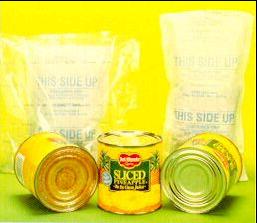
| The can on the left above, was shipped without the clay-based
desiccant attached to pallet loads, right. |
Container Dri activates whenever the dew point is reached and condensation
starts to form inside the cargo container. The dew point itself varies depending
on a number of factors including temperature and humidity. When product reaches
its destination, the pouches are removed and discarded. "You could feel the
difference between Container Dri and silica gel," says Janice Ma, a Del Monte
researcher involved in the project. "When you picked up the Container Dri,
it was heavy, soaked with water, while the silica gel hadn't absorbed nearly
as much moisture."
The 10x5 3/4x1-in. pouches are either laid on the floor of cargo containers
or are taped at intervals atop pallet loads as they are loaded inside. Seventeen
pallets, with 100 cases per pallet, are loaded into each sealed container;
the same quantity of desiccant is used each time. Cargo containers are loaded
in Bugo (Philippines), shipped to Kaohsiung, Taiwan, for transfer to a larger
vessel (after storage time on the docks). Product enters the U.S. via one
of three ports: Seattle, Oakland or Los Angeles.
Del Monte reports an extremely high success rate in eliminating moisture
damage, resulting in savings that run into the millions of dollars, primarily
from recovered product and lower insurance premiums. Inspections are now
limited to an occasional monitoring of humidity via probes placed in an
occasional cargo container. Although the company began using the desiccant
in April '94, "We waited a full year before calling the program a success,"
says Koberstein, "to make sure we went through every season and every
factor that could occur in a 12-month cycle.
Since using Container Dri we've had a 100-percent success rate, zero failures
and no damage claims. "
Package having cup with beveled sealing flange
US Patent Issued on November 18, 2003
Inventor(s): James A. Porter III, Terry L. Koberstein, David K. Cosgrove
Assignee: Del Monte Corporation
Abstract:
A package for foodstuffs including a cup and a lid. The cup includes an opening
surrounded by a flange. The flange has a sealing surface adjacent the opening
and a beveled surface spaced outwardly of the sealing surface. The beveled
surface extends along a periphery of the flange. The sealing surface has
an inner radius R1 and an outer radius R2, the outer radius R2 defining the
juncture between the sealing surface and the beveled surface. The beveled
surface extends at a predetermined angle with respect to the sealing surface.
The lid includes a tab extending outward of the periphery of the flange.
The lid is affixed to the sealing surface thereby sealing the opening of
the cup. The lid is not affixed to a substantial portion of the beveled surface.
The lid and the sealing surface are adapted to release upon exertion of a
predetermined pulling force on the tab.
Claims:
What is claimed is:
1. A package for foodstuffs comprising;
a cup having an opening surrounded by a flange, said flange having a
substantially planar inner sealing surface adjacent said opening and an outer
beveled surface spaced outwardly of said sealing surface, said beveled surface
extending along a periphery of said flange; and a lid having a tab extending
outward of said periphery of said flange, said lid affixed to said substantially
planar inner sealing surface thereby sealing said opening of said cup.
2. The package of claim 1 wherein said lid is not affixed to a substantial
portion of said beveled surface.
3. The package of claim 1 wherein said lid is not affixed to said beveled
surface.
4. The package of claim 1 wherein said beveled surface extends at an angle
of at least approximately 8° with respect to said sealing surface.
5. The package of claim 1 wherein said beveled surface extends at an angle
of approximately 10° with respect to said sealing surface.
6. The package of claim 1 wherein said beveled surface extends at an angle
of less than approximately 12° with respect to said sealing surface.
7. The package of claim 1 wherein said sealing surface has an inner radius(R1)
and an outer radius(R2) said outer radius(R2) defining the juncture between
said sealing surface and said beveled surface.
8. The package of claim 7 wherein the difference between said outer radius(R2)
and said inner radius(R1) is at least approximately 0.080 inches.
9. The package of claim 7 wherein the difference between said outer radius(R2)
and said inner radius(R1) is approximately 0.100 inches.
10. The package of claim 7 wherein the difference between said outer radius(R2)
and said inner radius(R1) is less than approximately 0.120 inches.
11. The package of claim 1 wherein said lid and said sealing surface are
adapted to release upon exertion of a predetermined pulling force on said
tab.
12. The package of claim 11 wherein said predetermined pulling force is
approximately 6 to 8 pounds.
13. The package of claim 11 wherein said predetermined pulling force is
approximately 3 to 5 pounds.
14. The package of claim 1 wherein said lid comprises an oxygen barrier.
15. The package of claim 1 wherein said lid is affixed to said sealing surface
by an adhesive bonding agent.
16. The package of claim 1 wherein said lid is affixed to said sealing surface
by an endless weld.
17. The package of claim 1 wherein said cup is plastic.
18. The package of claim 1 wherein said cup is round.
19. A package for foodstuffs comprising;
a cup having an opening surrounded by a flange, said flange having a
substantially planar inner sealing surface adjacent said opening and a beveled
surface spaced outwardly of said sealing surface, said beveled surface extending
along a periphery of said flange; and
a lid having a tab extending outward of said periphery of said flange, said
lid affixed to 1said substantially planar inner sealing surface thereby sealing
said opening of said cup, wherein said lid is not affixed to a substantial
portion of said beveled surface, wherein said lid and said sealing surface
are adapted to release upon exertion of a predetermined pulling force on
said tab of approximately 6 to 8 pounds.
20. The package of claim 19 wherein said beveled surface extends at an angle
of at approximately 8° to 12° with respect to said sealing surface.
21. The package of claim 19 wherein said sealing surface has an inner radius(R1)
and an outer radius(R2) said outer radius(R2) defining the juncture between
said sealing surface and said beveled surface, wherein the difference between
said outer radius(R2) and said inner radius(R1) is in the range of approximately
0.080 inches and approximately 0.120 inches.
22. The package of claim 19 wherein said predetermined pulling force is
approximately 3 to 5 pounds.
Description
BACKGROUND OF THE INVENTION
1. Field of the Invention
The present invention relates to a new and improved package for foodstuffs.
More particularly, the present invention relates to a package having a cup
with a beveled sealing flange.
2. Description of Related Art
A wide variety of hermetically sealed packages suitable for containing foodstuffs
are known. One conventional package widely used for containing foodstuffs
includes a plastic cup having a removable film seal. In particular, the plastic
cup includes a sealing flange to which the removable film seal is attached.
Preferably, the cup and the film seal of the conventional package are adapted
to allow a consumer to open the package, that is, remove the film seal from
the cup with minimal effort to gain access to the foodstuffs contained within
the package. The film seal can be engineered to provide a reduced peel level
or predetermined amount of force required to remove the film seal from the
cup. However, reducing the peel level disadvantageously affects other critical
functional requirements of the package. For example, reducing the peel level
proportionately increases the possibility of the package bursting and/or
leaking. Re-engineering the film seal is insufficient to effect a significant
reduction in the opening force of the package because conventional sealing
equipment has a wide variation of operating parameters, including temperature,
seal time, pressure and other factors, which must be considered when designing
the package. In addition to the sealing equipment, a thermo-processing
environment (retort) must be compatible with the materials of the package.
Conventional packing and sealing equipment is generally standardized to
accommodate cups having a one-quarter inch sealing flange. Disadvantageously,
the use of a one-quarter inch sealing flange provides a rather large contact
area between the film seal and the cup thus requiring a considerable amount
of force on the part of a consumer to remove the film seal from the cup.
Although use of a narrow flange has been contemplated, it has been determined
that narrow flanges are not compatible with current tooling. In particular,
due to the inherent play found in conventional sealing equipment, use of
a smaller, for example, a one-eighth inch sealing flange is insufficient
to properly seal the film seal to the cup. Although, such configuration may
reduce the amount of force necessary to remove the film seal from the cup,
such configuration is insufficient to overcome pressures exerted upon the
packages during retorting, shipping and distribution which may disadvantageously
blow the film seal off the cup, or otherwise result in a leaking seal.
What is needed is a new and improved package for foodstuffs which overcomes
the above and other disadvantages of known packages.
SUMMARY OF THE INVENTION
In summary, one aspect of the present invention is directed to a package
for foodstuffs. The package generally includes a cup and a lid. The cup includes
an opening surrounded by a flange. The flange has a sealing surface adjacent
the opening and a beveled surface spaced outwardly of the sealing surface.
The beveled surface extends along a periphery of the flange. The sealing
surface has an inner radius R1 and an outer radius R2, the outer radius R2
which defines the juncture between the sealing surface and the beveled surface.
The beveled surface extends at a predetermined angle with respect to the
sealing surface. The lid includes a tab extending outward of the periphery
of the flange. The lid is affixed to the sealing surface thereby sealing
the opening of the cup. The lid is not affixed to a substantial portion of
the beveled surface.
The lid and the sealing surface are adapted to release upon exertion of a
predetermined pulling force on the tab. The predetermined pulling force is
less than approximately 8 pounds and is preferably approximately 3 to 5 pounds.
An object of the present invention is to provide a new and improved package
suitable for containing foodstuffs and other substances.
Yet another object of the present invention is to provide a package including
a lid and a cup having a reduced contact area while maintaining the overall
dimensions of the cup.
It is a further object of the present invention to provide a packaging adapted
for reducing the amount of force on the part of a consumer and/or user required
to remove the lid from the cup while maintaining the structural integrity
of the package.
The accompanying drawings, which are incorporated in and form a part of this
specification, illustrate embodiments of the invention and, together with
the description, serve to explain the principles of the invention.
BRIEF DESCRIPTION OF THE DRAWINGS
FIG. 1 is a side elevational view of a package for foodstuffs in accordance
with the present invention, the package including a cup and a lid affixed
to the cup.
FIG. 2 is a bottom plan view of the cup and lid shown in FIG. 1.
FIG. 3 is an enlarged detailed view of a portion of a prior art package for
foodstuffs.
FIG. 4 is an enlarged detailed view of a portion of the cup of the present
invention shown in FIG. 1.
DESCRIPTION OF THE PREFERRED EMBODIMENTS
Reference will now be made in detail to the preferred embodiments of the
invention, examples of which are illustrated in the accompanying drawings.
While the invention will be described in conjunction with the preferred
embodiments, it will be understood that they are not intended to limit the
invention to those embodiments. On the contrary, the invention is intended
to cover alternatives, modifications and equivalents, which may be included
within the spirit and scope of the invention as defined by the appended claims.
Turning now to the drawings, wherein like components are designated by like
reference numerals throughout the various figures, attention is directed
to FIGS. 1 and 2 which illustrate a package 30 for foodstuffs in accordance
with the present invention. Package 30 is particularly suited for containing
single-serving portions of fruits and other foodstuffs. Generally, package
30 includes a cup 31 and a lid 32. In the illustrated embodiment, cup 31
and lid 32 are circular, however, one should appreciate that other shapes
can be utilized in accordance with the present invention. In particular,
the sealing flange of the cup can be oval, triangular, square, rectangular,
or any other suitable shape.
Cup 31 of the present invention includes a thin-walled receptacle 36, an
opening 37 formed in receptacle 36, and a sealing flange 38 which surrounds
the opening in a manner similar to that of conventional packages. In one
embodiment of the present invention, cup 31 is formed of plastic and is
preferably formed of polypropylene. One should appreciate, however, that
other suitable materials can be used in accordance with the present invention.
Unlike the sealing flange 41 of a prior art package 42 which has a planar
sealing surface 43, as shown in FIG. 3, sealing flange 38 of the present
invention includes a substantially planar inner sealing surface 47 adjacent
opening 37 and an outer beveled surface 48 spaced outwardly of sealing surface
47, as shown in FIG. 4. In particular, beveled surface 48 extends along a
periphery 49 of sealing flange 38 outside of sealing surface 47 and extends
downwardly and outwardly from inner sealing surface 47 of sealing flange
38.
Beveled surface 48 extends at an angle with respect to the sealing surface.
In one embodiment, beveled surface 48 extends at an angle of approximately
8° to 12°, and more preferably, approximately 10°.
The illustrated embodiment includes a beveled surface that is substantially
linear and forms a frustoconical surface. One should appreciate that the
slope of the beveled surface need not be linear but instead can be curved
in accordance with the present invention. For example, the beveled surface
can form a concave juncture or fillet between the sealing surface and the
outer peripheral edge of the sealing flange, provided the beveled surface
is substantially remote from the lid. Alternatively, the beveled surface
can form a convex juncture or rounded chamfer between the sealing surface
and the outer peripheral edge. One should appreciate that, in the case a
curved profile is utilized, the profile preferably extends uniformly around
the circumference of the flange in order to minimize inconsistency and the
possibility of leakage.
Sealing surface 47 has an inner radius R1 and an outer radius R2. The outer
radius R2 defines the juncture between sealing surface 47 and beveled surface
48.
The difference R? between the outer radius R2 and the inner radius R1 can
vary in accordance with present invention but is less than the width of the
flange. Preferably the difference R? between the outer radius R2 and the
inner radius R1 is between approximately 0.080 inches and 0.120 inches. For
example, the difference between the outer radius R2 and the inner radius
R1 can be approximately 0.080 inches, approximately 0.100 inches, approximately
0.120 inches, or other suitable dimension in order to provide a desired
predetermined pulling force required for a consumer to remove lid 32 from
cup 31, as discussed below.
In one embodiment of the present invention, lid 32 includes a flexible seal
film that is composed of multiple layers. Preferably, the film seal of lid
32 includes at least layer one that is impermeable to air and thus forms
an oxygen barrier layer for hermetically sealing a foodstuff within the package
30. Preferably, the film of lid 32 includes an adhesive bonding agent to
facilitate attaching lid 32 to cup 31. Alternatively, the lid can be affixed
to the sealing surface with an endless weld or other suitable means within
the scope of the present invention.
Lid 32 includes a tab 53 which extends outwardly of periphery 49 of sealing
flange 38. Lid 32 is adhesively affixed to sealing surface 47 of sealing
flange 38 thereby sealing opening 37 of cup 31. Importantly, lid 32 is not
affixed to at least a substantial portion of beveled surface 48. Preferably,
lid 32 is not affixed to any portion of beveled surface 48. However, one
should appreciate that lid 32 may inadvertently be affixed to a minimal portion
of the beveled surface due to the inherent play and tolerances found in
conventional packing and sealing equipment. Preferably, lid 32 contacts no
more than approximately 10% of beveled surface 48, and most preferably no
more than approximately 20% of the beveled surface.
The configuration of sealing flange 38 of the present invention provides
a package in which a desired predetermined pulling force of less than
approximately 8 pounds, and preferably between approximately 3 to 5 pounds,
as necessary to remove lid 32 from cup 31. In particular, a consumer and/or
user can grip tab 53 and pull the tab away from sealing flange 38 of cup
32 with minimal effort. For example, in one embodiment, the package has a
pulling force of approximately 6 to 8 pounds as determined by a pull test
conducted with a 23° angle, full panel peel test on the cup.
Lid 32 is sealed to cup 31 with conventional packing and sealing equipment.
In one embodiment of the present invention, lid 32 is sealed to cup 31 at
approximately 375° F. utilizing an approximate 0.70 second dwell-time,
and at approximately 50 psi equipment conditions. Preferably, package 30,
as well as the foodstuffs contained therein, are prepared in a retort
environment. Preferably, package 30 is also designed and configured to withstand
temperatures to 230° F. and pressures up to two bars. One should appreciate,
however, that the package need not be prepared in a retort environment.
Sealing flange 38 is modified in such a way that the overall contact area
between lid 32 and flange 38 of cup 31 is reduced without reducing the overall
dimension of sealing flange 38. In particular, beveled surface 48 reduces
the area of sealing surface 47 thus reducing the overall contact area between
lid 32 and sealing surface 47. For example, the overall dimension of sealing
flange 38, that is, the outside radius R3 of sealing flange 38 does not differ
from that of prior art sealing flange 41 of the prior art package shown in
FIG. 3. However, the total contact area between lid 32 and sealing flange
38 of the present invention is significantly less that than of the prior
art package shown in FIG. 3.
The total contact area between lid 32 and sealing flange 38 of the present
invention is the substantially planar area of sealing surface 47 which is
defined by inner radius R1 and outer radius R2, as shown in FIG. 4. In contrast,
the total contact area of prior art sealing flange 41 is the entire sealing
surface 43 which is defined by the inside radius R4 and the outside radius
R5 of sealing flange 41, as shown in FIG. 3. The total contact area between
lid 32 and sealing flange 38 of the present invention is significantly reduced
as compared to prior art configurations. In one embodiment, the total contact
area is approximately one-quarter square inch. Preferably, the total contact
area is less than 0.25 square inches. The reduced contact area configuration
reduces the opening force required by a consumer to pull and peel lid 32
away from cup 31 by approximately 15% to 20% while maintaining finished product
integrity.
A critical functional requirement for the package of the present invention
is to maintain a package integrity having a burst value, as determined by
a restrained burst test with 1/8 inch gap in the tester, of at least
approximately 8 psi, and preferably approximately 9 psi burst value. In
particular, the configuration of the sealing flange of the present invention
provides a design that withstands pressures which may be encountered during
shipping and distribution of the package. For example, the sealing flange
of the present invention provides a design which withstands a predetermined
burst value of at least approximately 9 psi. This configuration also minimizes
leakage of the package after retort. For example, the sealing flange of the
present invention may provide a configuration in which leakage occurs in
less than one package in 4000 following assembly of the cup and lid and after
retort.
In operation and use a consumer and/or user grips tab 53 of lid 32 and pulls
lid 32 away from cup 31 in order to gain access to the contents contained
within package 30. The consumer can partially or entirely remove lid 32 from
cup 31 in order to access the contents of the package in a well known manner.
As noted above, the package of the present invention is designed configured
to allow the consumer to remove the lid from the cup using minimal force.
For example, the amount of force required on the part of the consumer to
pull and peel lid 32 away from cup 31 preferably ranges from approximately
six pounds to eight pounds.
Advantageously, sealing flange 38 of the present invention provides a
configuration which reduces the opening force required by a consumer to open
package 30 while maintaining the structural integrity of package 30. As noted
above, sealing flange 38 is modified in such a way that the overall contact
area between lid 32 and flange 38 of cup 31 is reduced without reducing the
overall dimension of sealing flange 38.
The foregoing descriptions of specific embodiments of the present invention
have been presented for purposes of illustration and description. They are
not intended to be exhaustive or to limit the invention to the precise forms
disclosed, and obviously many modifications and variations are possible in
light of the above teaching. The embodiments were chosen and described in
order to best explain the principles of the invention and its practical
application, to thereby enable others skilled in the art to best utilize
the invention and various embodiments with various modifications as are suited
to the particular use contemplated. It is intended that the scope of the
invention be defined by the Claims appended hereto and their equivalents.
Application
No. 944733 filed on 2001-08-31
Current US Class
220/359.2 , Including gripping means for removing closure (e.g., pull tab)
220/359.4 , Including heat sealed retaining means 229/123.1 , Nonunitary,
peelable closure or securing element (i.e., not of one-piece construction
with the box) 426/123 Having destructive type opening utilizing tearing appendage
Field of Search
206/467 , Movable or detachable housing closure 206/484 , LAMINATE SHEET
PACKET 215/12.1 , MULTILAYER BARRIER STRUCTURE 215/232 , Retained by bonding
or adhesive means 220/359.1 , Removable closure retained by adhesive or fusion
means 220/359.2 , Including gripping means for removing closure (e.g., pull
tab) 220/359.3 , Multilayer 220/359.4 , Including heat sealed retaining means
220/359.5 , Soldered 220/656 , ONE-PIECE, REINFORCED OPEN END EDGE 220/657
, Flange 220/659 , Molded 229/123.1 , Nonunitary, peelable closure or securing
element (i.e., not of one-piece construction with the box) 426/123 Having
destructive type opening utilizing tearing appendage
Examiners
Primary: Robin Hylton
Attorney, Agent or Firm
Dorsey & Whitney LLP
US Patent References
5039001, 6082533 |